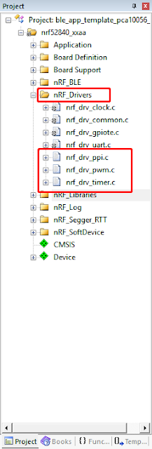
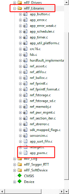
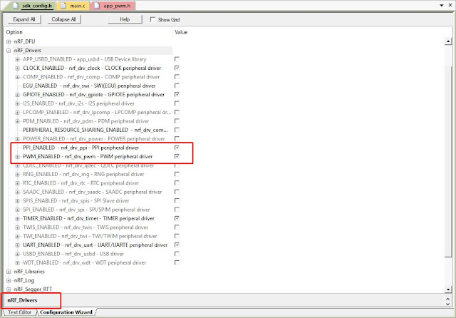
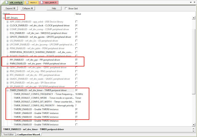
What can we do if we need those drivers or libraries? nordic semiconductor's websites don't have any message about exactly how to use an example from the nRF5 SDK in combination with the mesh stack.
In this article, I will present
- how to integrate external drivers or libraries in BLE SDK into ble MESH SDK
- activate them with SEGGER embedded Studio
I use UART function for example.
PLATFORM:
device: nrf52832_xxaa
softdevice:S132
project: light_switch_server_nrf52832_xxaa_s132_3.1.0
ble SDK: nRF5_SDK_14.2.0_17b948a
ble MESH SDK: nrf5_SDK_for_Mesh_v1.0.1_src
STEP 0 : copy necessary drivers file to ble MESH sdk
copy "common" folder
from
..\nRF5_SDK_14.2.0_17b948a\components\softdevice\common
to
..\nrf5_SDK_for_Mesh_v1.0.1_src\external\softdevice

copy clock/common/power/uart 4 folders
from
..\nRF5_SDK_14.2.0_17b948a\components\drivers_nrf
to
..\nrf5_SDK_for_Mesh_v1.0.1_src\external\nRF5_SDK_14.2.0_17b948a\components\drivers_nrf

copy uart/experimental_log/experimental_section_vars/fifo 4 folders
from
..\nRF5_SDK_14.2.0_17b948a\components\libraries
to
..\nrf5_SDK_for_Mesh_v1.0.1_src\external\nRF5_SDK_14.2.0_17b948a\components\libraries

STEP 1: include divers files to SEGGER embedded Studio preprocessor
click project"light_switch_server", and select "Edit options.."/Preprocessor/ User Include Directories

add the following path into that blue blank:
../../../external/nRF5_SDK_14.2.0_17b948a/components/libraries/uart;
../../../examples/light_switch_idesyn_sandbox/server/src;
../../../external/nRF5_SDK_14.2.0_17b948a/components/drivers_nrf/common;
../../../external/nRF5_SDK_14.2.0_17b948a/components/libraries/experimental_log;
../../../external/nRF5_SDK_14.2.0_17b948a/components/libraries/experimental_section_vars;
../../../external/nRF5_SDK_14.2.0_17b948a/components/libraries/experimental_log/src;
../../../external/nRF5_SDK_14.2.0_17b948a/components/drivers_nrf/power;
../../../external/nRF5_SDK_14.2.0_17b948a/components/drivers_nrf/clock;
../../../external/nRF5_SDK_14.2.0_17b948a/components/drivers_nrf/uart;
../../../external/nRF5_SDK_14.2.0_17b948a/components/libraries/fifo;
../../../external/softdevice/common;
STEP 2: include C files to project
I create nRF_Drivers_Import/nRF_Library_Import 2 folders to put C files imported from SDK14
add to nRF_Drivers_Import:
- nrf_drv_common.c
- nrf_drv_clock.c
- nrf_drv_uart.c
- nrf_drv_power.c
add to nRF_Library_Import:
- app_fifo.c
- app_uart_fifo.c
- retarget.c

STEP 3: initialize UART in main.c
add the following code in main.c
about line 60
#include "app_uart.h"
#if defined (UART_PRESENT)
#include "nrf_uart.h"
#endif
#if defined (UARTE_PRESENT)
#include "nrf_uarte.h"
#endif

#define UART_HWFC   APP_UART_FLOW_CONTROL_DISABLED
#define UART_TX_BUF_SIZE 256                         /**< UART TX buffer size. */
#define UART_RX_BUF_SIZE 256                         /**< UART RX buffer size. */
#define DATA_LEN   (6)
static uint8_t data_array[DATA_LEN];
static uint8_t index = 0;
about line 130
void uart_event_handle(app_uart_evt_t * p_event)
{

    switch (p_event->evt_type)
    {
        case APP_UART_DATA_READY:
            UNUSED_VARIABLE(app_uart_get(&data_array[index]));
            break;

        case APP_UART_COMMUNICATION_ERROR:
            ERROR_CHECK(p_event->data.error_communication);
            break;

        case APP_UART_FIFO_ERROR:
            ERROR_CHECK(p_event->data.error_code);
            break;

        default:
            break;
    }
}

static void uart_init(void)
{
 uint32_t err_code;
 const app_uart_comm_params_t comm_params =
 {
                 RX_PIN_NUMBER,
   TX_PIN_NUMBER,
   RTS_PIN_NUMBER,
   CTS_PIN_NUMBER,
   UART_HWFC,
   false,
   NRF_UART_BAUDRATE_115200
 };

    APP_UART_FIFO_INIT(&comm_params,
   UART_RX_BUF_SIZE,
   UART_TX_BUF_SIZE,
   uart_event_handle,
   APP_IRQ_PRIORITY_LOWEST,
   err_code);

    ERROR_CHECK(err_code);
}
in main function line 180
    __LOG(LOG_SRC_APP, LOG_LEVEL_INFO, "----- BLE Mesh Light Switch Server Demo -----\n");
    __LOG(LOG_SRC_APP, LOG_LEVEL_INFO, "----- program by AgathaKuan\n");

    hal_leds_init();
    uart_init();

    printf("system start\r\n");
STEP 4: include "nrf_mesh_sdk.h" to app_uart_fifo.c
open app_uart_fifo.c
add about line 40
#include "sdk_common.h"
#include "nrf_mesh_sdk.h"
STEP 5: modify APP_ERROR_CHECK( ) function as ERROR_CHECK( )
open app_uart_fifo.c
about 200 app_uart_get( ) function:
change APP_ERROR_CHECK (uart_err_code) to ERROR_CHECK (uart_err_code)
uint32_t app_uart_get(uint8_t * p_byte)
{
    ASSERT(p_byte);
    bool rx_ovf = m_rx_ovf;

    ret_code_t err_code =  app_fifo_get(&m_rx_fifo, p_byte);

    // If FIFO was full new request to receive one byte was not scheduled. Must be done here.
    if (rx_ovf)
    {
        m_rx_ovf = false;
        uint32_t uart_err_code = nrf_drv_uart_rx(&app_uart_inst, rx_buffer, 1);

        // RX resume should never fail.
        ERROR_CHECK(uart_err_code);
    }

    return err_code;
}
STEP 6: add sdk_config.h near by main.c
copy sdk_config.h
from
..\nRF5_SDK_14.2.0_17b948a\examples\ble_peripheral\ble_app_template
to
..\nrf5_SDK_for_Mesh_v1.0.1_src\examples\light_switch\server\src

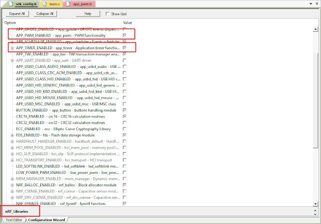
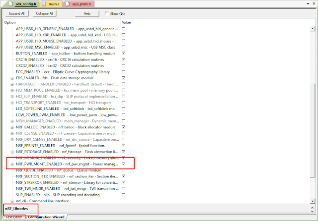
STEP 7: modify sdk_config.h to enable UART
add these about line 3004
// <h> nRF_Libraries
//==========================================================
// <q> APP_FIFO_ENABLED  - app_fifo - Software FIFO implementation


#ifndef APP_FIFO_ENABLED
#define APP_FIFO_ENABLED 1
#endif
then add these about line 3080
// <e> APP_UART_ENABLED - app_uart - UART driver
//==========================================================
#ifndef APP_UART_ENABLED
#define APP_UART_ENABLED 1
#define APP_UART_DRIVER_INSTANCE 0
#endif
then add these about line 3506
// <q> RETARGET_ENABLED  - retarget - Retargeting stdio functions


#ifndef RETARGET_ENABLED
#define RETARGET_ENABLED 1
#endif
about line 2724
// <e> UART_ENABLED - nrf_drv_uart - UART/UARTE peripheral driver
//==========================================================
#ifndef UART_ENABLED
#define UART_ENABLED 1
#endif
#if  UART_ENABLED
// <o> UART_DEFAULT_CONFIG_HWFC  - Hardware Flow Control

// <0=> Disabled
// <1=> Enabled

#ifndef UART_DEFAULT_CONFIG_HWFC
#define UART_DEFAULT_CONFIG_HWFC 0
#endif

// <o> UART_DEFAULT_CONFIG_PARITY  - Parity

// <0=> Excluded
// <14=> Included

#ifndef UART_DEFAULT_CONFIG_PARITY
#define UART_DEFAULT_CONFIG_PARITY 0
#endif

// <o> UART_DEFAULT_CONFIG_BAUDRATE  - Default Baudrate

// <323584=> 1200 baud
// <643072=> 2400 baud
// <1290240=> 4800 baud
// <2576384=> 9600 baud
// <3862528=> 14400 baud
// <5152768=> 19200 baud
// <7716864=> 28800 baud
// <10289152=> 38400 baud
// <15400960=> 57600 baud
// <20615168=> 76800 baud
// <30801920=> 115200 baud
// <61865984=> 230400 baud
// <67108864=> 250000 baud
// <121634816=> 460800 baud
// <251658240=> 921600 baud
// <268435456=> 57600 baud

#ifndef UART_DEFAULT_CONFIG_BAUDRATE
#define UART_DEFAULT_CONFIG_BAUDRATE 30801920
#endif

// <o> UART_DEFAULT_CONFIG_IRQ_PRIORITY  - Interrupt priority


// <i> Priorities 0,2 (nRF51) and 0,1,4,5 (nRF52) are reserved for SoftDevice
// <0=> 0 (highest)
// <1=> 1
// <2=> 2
// <3=> 3
// <4=> 4
// <5=> 5
// <6=> 6
// <7=> 7

#ifndef UART_DEFAULT_CONFIG_IRQ_PRIORITY
#define UART_DEFAULT_CONFIG_IRQ_PRIORITY 7
#endif

// <q> UART_EASY_DMA_SUPPORT  - Driver supporting EasyDMA


#ifndef UART_EASY_DMA_SUPPORT
#define UART_EASY_DMA_SUPPORT 1
#endif

// <q> UART_LEGACY_SUPPORT  - Driver supporting Legacy mode


#ifndef UART_LEGACY_SUPPORT
#define UART_LEGACY_SUPPORT 1
#endif

// <e> UART0_ENABLED - Enable UART0 instance
//==========================================================
#ifndef UART0_ENABLED
#define UART0_ENABLED 1
#endif
#if  UART0_ENABLED
// <q> UART0_CONFIG_USE_EASY_DMA  - Default setting for using EasyDMA


#ifndef UART0_CONFIG_USE_EASY_DMA
#define UART0_CONFIG_USE_EASY_DMA 1
#endif

#endif //UART0_ENABLED
// </e>

// <e> UART_CONFIG_LOG_ENABLED - Enables logging in the module.
//==========================================================
#ifndef UART_CONFIG_LOG_ENABLED
#define UART_CONFIG_LOG_ENABLED 0
#endif
#if  UART_CONFIG_LOG_ENABLED
// <o> UART_CONFIG_LOG_LEVEL  - Default Severity level

// <0=> Off
// <1=> Error
// <2=> Warning
// <3=> Info
// <4=> Debug

#ifndef UART_CONFIG_LOG_LEVEL
#define UART_CONFIG_LOG_LEVEL 3
#endif

// <o> UART_CONFIG_INFO_COLOR  - ANSI escape code prefix.

// <0=> Default
// <1=> Black
// <2=> Red
// <3=> Green
// <4=> Yellow
// <5=> Blue
// <6=> Magenta
// <7=> Cyan
// <8=> White

#ifndef UART_CONFIG_INFO_COLOR
#define UART_CONFIG_INFO_COLOR 0
#endif

// <o> UART_CONFIG_DEBUG_COLOR  - ANSI escape code prefix.

// <0=> Default
// <1=> Black
// <2=> Red
// <3=> Green
// <4=> Yellow
// <5=> Blue
// <6=> Magenta
// <7=> Cyan
// <8=> White

#ifndef UART_CONFIG_DEBUG_COLOR
#define UART_CONFIG_DEBUG_COLOR 0
#endif

#endif //UART_CONFIG_LOG_ENABLED
// </e>

#endif //UART_ENABLED
// </e>
STEP 8:build project / download to your device
click build/build configuration/ clean "light_switch_server"/ build "light_switch_server"

click target/connect JLink/ Download "light_switch_server" /Verify "light_switch_server"

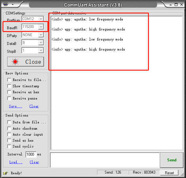
then open com port, you can see

and that means we exactly activate UART function.
NOTE:
1. nordic semiconductor's websites don't have any message about exactly how to use an example from the nRF5 SDK in combination with the mesh stack. However, in this example, I prove that add/ include all necessary files and modify configuration , we can use hardware externals APIs from nRF5 SDK to ble MESH SDK.
REFERENCE:
1. http://infocenter.nordicsemi.com/index.jsp?topic=%2Fcom.nordic.infocenter.meshsdk.v0.10.0%2Fmd_doc_getting_started_how_to_nordicSDK.html&cp=4_1_0_0_0
2. https://devzone.nordicsemi.com/f/nordic-q-a/19549/segger-studio-tutorial-user-include-directories-has-no-effect---no-such-file
3.http://infocenter.nordicsemi.com/index.jsp?topic=%2Fcom.nordic.infocenter.meshsdk.v1.0.0%2FLIBRARIES.html&cp=4_1_0_4
