2018年1月12日 星期五

JN516x Start (1): how to start JenOS development environment

JN5169 Start (1): how to start JenOS development environment

Before starting to program, we need to prepare our development environment, but there is no a document for developers to step-by-step install IDE, SDK, and plugins to start there, and that  this article written about.

for "How to install JenOS configuration Dialog Editor", please jump to STEP 6

JN5169 Start (2) is about how to program your  .bin into your JN516x chip.


STEP 0. download from NXP website.

we need 4 files download from NXP
1. JN-SW- 4141 BeyondStudio for NXP  (not LOWER then v13.08)
2. JN-SW- 4168 JN516x SDK
3. JN-SW- 4107 JN51xx Production Flash Programmer
4. JN-SW- 1171 An example code for JN5169

STEP 1.  install BeyondStudio for NXP
download  from NXP website and unzip


press right button and (A) (excution as system administrator) and  "agree"


then press "next" until "choose install location".
I choose default location in
C: \NXP\bstudio_nxp\

and press "install"


start installing.....


installation complete


in C:\ we can see file of BeyondStudio for  NXP


STEP 2.   install JN-SW-4168 SDK for JN516X
download from the same webpage and unzip it.


press right button and (A)  (excution as system administrator) and  "agree"


then press "next" until "choose install location".
I choose default location in
C: \NXP\bstudio_nxp\

and press "install"


installation complete


and now we can see in
C:\NXP\bstudio_nxp\sdk
It will be like this


STEP 2.install JN51xx Production Flash Programmer

download from here and unzip


press right button and (A)  (excution as system administrator) and  "agree"


then press "next" until "choose install location".
I choose default location in
C: \NXP\ProductionFlashProgrammer


After installation completed, in C:\NXP\ProductionFlashProgrammer
we can see:


STEP 3. download JN-SW- 3098 (An example code for JN5169)
download from here and unzip it


STEP 4. import  example code
(1) copy "JN-AN-1171-ZigBee-LightLink-Demo" folder
C:\..\..\..\JN-AN-1171\JN-AN-1171-ZigBee-LightLink-Demo

to C:\NXP\bstudio_nxp\workspace


(2) doudle press "bstudio_nxp.exe" to start beyond studio


select workspace  at
C:\NXP\bstudio_nxp\workspace and press "OK"


(3) check BeyondStudio edition
press "help" ->  "about BeyondStudio for NXP"
then we will see: Build  1308


(4) import project

press "file" -> "import"
select "General"->"Existing projects into Workspace"


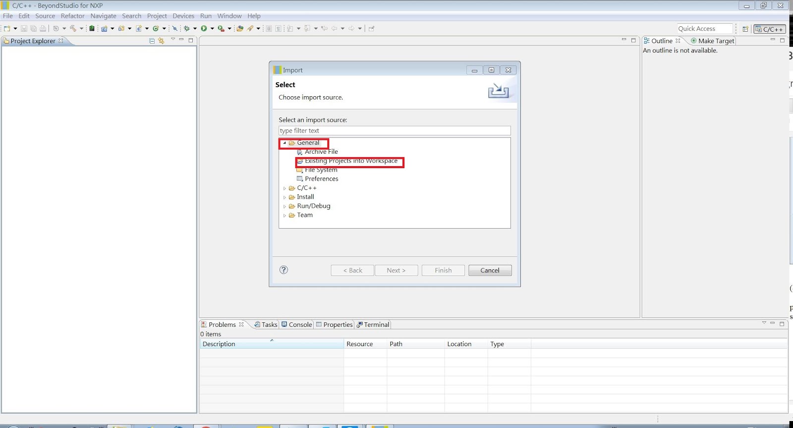
press "select root directory"->"browse"
and select JN-AN-1171 in workspace


select "JN-AN-1171-ZigBee-LightLink-Demo" folder and press "finish"


now we successfully import in project


STEP 5.compile example code
press the hammer button and select a project


start building


finish


STEP 6. install Jennic configuration Editor tool
JN51XX use a kind of RTOS called "JenOS", and "JenOS" use a graphical interface
configuration Dialog 
to register hardware interrupts, timers...etc.

before we install it, if we press any of ".oscfgdiag" , we will see:


and we have to install a eclipse plugin to let it be a graphical interface
this installer is already in JN-SW-4168
what we need to do is installing it into BeyondStudio

open BeyondStudio, and press "Help"->"install new software"


press "Add..."->"Local..."


select C:\NXP\bstudio_nxp\sdk\JN-SW-4168\Tools\Eclipse_plugins\com.nxp.sdk.update_site


and you will see "Jennic ZBPro SDK" ->"Jennic configuration Editor"
select all and press "next"


accept the agreement and press "finish"


start installing...


After installation completed, you have to restart BeyondStudio


After restart, select any ".oscfgdiag" we will see:


Now we successfully compile the example code and make sure that our Development Environment is completed prepared.


reference:

1.NXP website
https://www.nxp.com/products/wireless-connectivity/proprietary-ieee-802.15.4-based/zigbee/zigbee-light-link:ZIGBEE-LIGHT-LINK

2. BeyondStudio for NXP Installation and User Guide

3. ZigBee Cluster Library User Guide (for ZLL/HA)

4. JN-UG-3099

5.JN-SW- 3098 Document


2017年9月19日 星期二

nRF51: button long-press & short-multi press implement without BSP

In some case, it is ineviatable to use ONE button as multi-type signal source.Thus, in this post, I demonstate how to discern the state of button-pressed via nRF51 SDK. This article is an implementation of the function to support button long-pressed and multi-pressed as specified signal without BSP supplying.

the following article is a simple implement of:

1. long press with customized interval
2. short- multi press
3. the hurried pressings might lead system crash, it needs protection, so I ingore any-button signal in the next 4 seconds

BUTTON 1 implemented to measure the pressing time (in 0.1 sec)
BUTTON 2 implemented for  receiving double press


SDK 11/ nRF51822

*about how to start your UART, please read this article


STEP 1 . add ..\..\..\..\..\..\components\libraries\gpiote


add these two files to your project


STEP 2. add button definition
add the code about line 58.

#include "app_button.h"
#include "app_gpiote.h"
#define BUTTON_DEBOUNCE_DELAY   10 
#define APP_GPIOTE_MAX_USERS             1  . 


STEP 3. buttons initialization
change func buttons_leds_init( ) like this

static void buttons_leds_init(bool * p_erase_bonds)
{
    bsp_event_t startup_event;

    uint32_t err_code = bsp_init(BSP_INIT_NONE,
                                 APP_TIMER_TICKS(30, APP_TIMER_PRESCALER), 
                                 bsp_event_handler);
    APP_ERROR_CHECK(err_code);
    
 
    static app_button_cfg_t p_button[] = {{BUTTON_1, APP_BUTTON_ACTIVE_LOW, NRF_GPIO_PIN_PULLUP, button_handler},
                                          {BUTTON_2, APP_BUTTON_ACTIVE_LOW, NRF_GPIO_PIN_PULLUP, button_handler},};

                                        
    APP_GPIOTE_INIT(APP_GPIOTE_MAX_USERS);
                      
  // Initializing the buttons.
    err_code = app_button_init(p_button, sizeof(p_button) / sizeof(p_button[0]), BUTTON_DEBOUNCE_DELAY);
    APP_ERROR_CHECK(err_code);
                      
    err_code = app_button_enable();
    APP_ERROR_CHECK(err_code);     

    err_code = bsp_btn_ble_init(NULL, &startup_event);
    APP_ERROR_CHECK(err_code);
                      
    *p_erase_bonds = (startup_event == BSP_EVENT_CLEAR_BONDING_DATA);
}

add button_handler( ) above buttons_leds_init ( )

static void button_handler(uint8_t pin_no, uint8_t button_action)
{ 
 uint32_t err_code;
 
 if (false != is_able_to_receiving_button_pressed_signal)
 {
  if(button_action == APP_BUTTON_PUSH)
  {
   switch(pin_no)
   {
    case BUTTON_1:
     PRINTF_MSG("press button 1 \r\n");
                 
     err_code = app_timer_start(measure_pressed_time_timer_id,PRESS_MEASURE_INTERVAL, NULL);
     APP_ERROR_CHECK(err_code);
     break;
         
    case BUTTON_2:   
    if (0 == button2_press_count)
    {   
     err_code = app_timer_start(double_press_id,DOUBLE_PRESS_READ_INTERVAL, NULL);
     APP_ERROR_CHECK(err_code);
    }
     
     break;          
      
    default:
     break;
   }
  }
  else if (button_action == APP_BUTTON_RELEASE)
  {
   switch(pin_no)
   {
    case BUTTON_1:                 
    PRINTF_MSG("button 1 release\r\n"); 
    uint32_t err_code;
    err_code = app_timer_stop(measure_pressed_time_timer_id);
    APP_ERROR_CHECK(err_code);
   
    printf("**button1_measured_count= %f totally**\r\n",button1_measured_count*0.1); 
    button1_measured_count= 0;
   
    is_able_to_receiving_button_pressed_signal= false;
    
    app_timer_start(button_restrict_id,BUTTON_RESTRICT_INTERVAL, NULL);
    break;
       
    case BUTTON_2:
    //PRINTF_MSG("button 2 release\r\n");
    
    button2_press_count= button2_press_count+1;
     
   if (DOUBLE_PRESS == button2_press_count)
   {
    is_able_to_receiving_button_pressed_signal = false;
    printf("detect double press !!\r\n");
     
    app_timer_start(button_restrict_id,BUTTON_RESTRICT_INTERVAL, NULL);
         
   } 
                    
    break;
       
    case BUTTON_3:
    break;
    
   default:
    break;
   }
  }
 }
 
}

STEP 4.  create timers

add the code about line.120

static uint16_t button1_measured_count= 0;
APP_TIMER_DEF(measure_pressed_time_timer_id); 
#define PRESS_MEASURE_INTERVAL               APP_TIMER_TICKS(100, APP_TIMER_PRESCALER)

static uint8_t button2_press_count;
APP_TIMER_DEF(double_press_id);
#define DOUBLE_PRESS_READ_INTERVAL        APP_TIMER_TICKS(1500, APP_TIMER_PRESCALER)
#define DOUBLE_PRESS                     (0x02)

static bool is_able_to_receiving_button_pressed_signal= true;

APP_TIMER_DEF(button_restrict_id);
#define BUTTON_RESTRICT_INTERVAL          APP_TIMER_TICKS(4000, APP_TIMER_PRESCALER)


add the code in timer_init ( )

uint32_t err_code;
  
err_code = app_timer_create(&measure_pressed_time_timer_id,
                               APP_TIMER_MODE_REPEATED,
                                button1_triggered_event_handler);
                   
APP_ERROR_CHECK(err_code);
  
  
err_code = app_timer_create(&double_press_id,
                               APP_TIMER_MODE_SINGLE_SHOT,
                              button2_triggered_event_handler);
                   
APP_ERROR_CHECK(err_code);
    
err_code = app_timer_create(&button_restrict_id,
                               APP_TIMER_MODE_SINGLE_SHOT,
                               button_restrict_handler);
                   
APP_ERROR_CHECK(err_code);

about the variable"is_able_to_receiving_button_pressed_signal ":

once the variable is_able_to_receiving_button_pressed_signal becomes false, the button pressed would be ignore, it will prevent system from crash of busy interruption.


add the code above timer_init ( )

static void  button1_triggered_event_handler(void * p_context)
{
 UNUSED_PARAMETER(p_context);

 button1_measured_count++;
 printf("recent counter = %f\r\n",button1_measured_count*0.1);
}


static void button2_triggered_event_handler(void * p_context)
{
 UNUSED_PARAMETER(p_context);
 uint32_t err_code;
 

 printf("button2_press_count= %d\r\n",button2_press_count); 
 button2_press_count= 0; 
}

 
static void button_restrict_handler(void * p_context)
{
 UNUSED_PARAMETER(p_context);
 
 is_able_to_receiving_button_pressed_signal = true;
 
 printf("can received button\r\n");
}

program and upload to your device.


STEP 5.Test

I long press button 1 for 10 sec then rapidly press button 2
the device can count how long I press button 1 and only receive 2 press of button 2

like this:


Reference:
https://github.com/NordicSemiconductor/nrf51-app-button-example/blob/master/main.c


2017年9月18日 星期一

nRF51: A precise description of DFU_OTA

In this article will have 2 parts.
part 1 will describe how to make a DFU zip  file
part 2 will describe how to resolve "DFUtarg" after program bootloader.
(which means you don't need to press S4 button)

PART 1.

STEP 1. hex file in ./build folder.

this is  BLE advertisng name of my device
you can see it in mobile app

and I try to OTA the device and change its advertisng name.


__________________________________________________________________________


I program again and change  DEVICE_NAME  to "nrf_agatha"
like this


find the .hex in
C:\..\pca10028\s130\arm5_no_packs\_build


STEP 2. install necessary application on PC
please install below applicaiton on your PC

nrf command line tool
https://www.nordicsemi.com/eng/Products/Bluetooth-low-energy/nRF51822

master control panel (MCP)
https://www.nordicsemi.com/eng/nordic/Products/nRF51-DK/nRF-MCP-x64/38907


STEP 3.command for making a zip file

copy this .hex file to
C:\Program Files (x86)\Nordic Semiconductor\Master Control Panel\3.10.0.14\nrf

open cmd.exe
and type the below command

cd C:\Program Files (x86)\Nordic Semiconductor\Master Control Panel\3.10.0.14\nrf
nrfutil.exe dfu genpkg --application nrf51422_xxac_s130.hex --application-version 0xffff --dev-revision 0xffff --dev-type 0xffff --sd-req 0xfffe nrf_agatha.zip

the result


and put nrf_agatha.zip to your mobile .


STEP 4.OTA upload test

start app nRF_Toolbox and press DFU


select .zip file


select device


start upload


disconnect


and you will the name change


PART 2. how to avoid "DFUtarg"
after programing

Softdevice  >
C:\..\nRF5x_SDK_11.0.0\components\softdevice\s130\hex

application >
(as your folder)

bootloader  >
C:\...\nRF5x_SDK_11.0.0\examples\dfu\bootloader\pca10028\dual_bank_ble_s130\arm5_no_packs\_build


go to
C:\Program Files (x86)\Nordic Semiconductor\nrf5x\bin

open cmd and type this command
cd C:\Program Files (x86)\Nordic Semiconductor\nrf5x\bin
nrfjprog.exe --family nrf51 --memwr 0x3fc00 --val 1

and type this
nrfjprog.exe --family nrf51 --reset


Note :
the above info had already write in my previous blogger, and this article just only for step-by-step